Kosár
0
Termék
Termék
(üres)
Nincs termék
Meghatározásra vár
Szállítás
0 Ft
Összesen
Termék a kosaradba helyezve
Mennyiség
Összesen
0 termék a kosaradban.
1 termék a kosaradban.
Termék összesen
Szállítás összesen
Meghatározásra vár
Összesen
Lucky Red 10 LED - LED DIY Kits kamat Elektronikus gyártás Vicces DIY Kreatív születésnapi ajándék
201715097931/2
Új termék
LED DIY Kits Interest Electronic Production Funny DIY Creative Birthday Gift1. Heart LED
1. Suite Features
XSD-18 Cycle Lamp is a kind of lamp which with great appearance of streamlines and color appearance. 18 pieces of Tri-color LED in this suite are divided into three groups and formed a heart-shaped pattern. The transistor oscillates the drive of circuit and let the Tri-color heart-shaped pattern roll in a clockwise direction and start light. The light looks more colorful and dynamic, especially when used at night. It's the best choice for the festive gift.PCB board Dimensions: 48MM * 51MM
2. Principle of Circuits
As it shown on below diagram, 18 pieces of LED have been divided into three groups: D1-D6,D7-D12 and D13-D18. All the three transistors try to breakover when the power is on. But only one of them could breakover at the first place due to the difference of the components. If the Q1 goes to breakover firstly, the D1-D6 will start light. As it shown on below diagram, 18 pieces of LED have been divided into three groups: D1-D6,D7-D12 and D13-D18. All the three transistors try to breakover when the power is on. But only one of them could breakover at the first place due to the difference of the components. If the Q1 goes to breakover firstly, the D1-D6 will start light. Because the collector voltage will be reduced which let the left side of C1 reduced to about 0V when the Q1 is on. As it cannot have a sudden change on the voltage of two ends of the capacitance, the base of Q2 has been reduced to 0V too. Then the Q2 is off and the D7-D12 turn off. But at this time, the high voltage of Q2 goes through C2 which make the voltage of Q3 base increased and let the Q3 on immediately. Then the D13-18 turn on. The collectors of both Q1 and Q3 are with low voltage during this period. And the D1-D6 and D13-D18 turn on, while D7-D12 turn off. But the collector voltage will be increased gradually after C1 has been charged by the power via R3. When the voltage is over 0.7V, Q2 enters a conducting state. And the collector voltage will increase which let the D13-D18 turn off. The circuit will operate according to this cycle that the 18 pieces of LED will be turned on by turns and 2 groups will be turned on at the same time. Note:
The position of the LEDs is adjustable. But the LEDs with the same color should be put in the same group in parallel.
The flash frequency will be changed according to the capacitanc
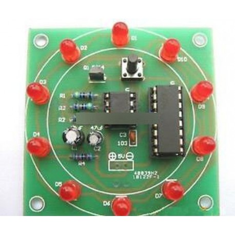
2. Lucky Red 10 LEDSuite parameters:Kit Model: LUCKY-10Supply voltage :3-5VDimensions: 58 * 58mmBoard FR-4 military grade A material1. Many soldering pads do not come off easily2 becomes less likely to occur from the bending (refer to the non-human case resulting bending), poor sheet with time and changes in the environment arising from bending.3. Impedance more stable and reliablePlate tolerance and stability of some of the parameters A material was very powerful interests in relative to some other sheet metal price of money.The function play: Wheel of Fortune is to predict the rotation of the disc to stop, and in the end will stop in which the position of the tool. Also can be used to estimate numbers game, electronic dice, lottery machine. Electronic Wheel of Fortune is in electronic way to reach the same functionality, this package of 10 LEDs configured in a circle, click the button, each LED sequence turns luminous, the flow speed is getting slower and slower and finally stopped at a only LED is no longer moving. The last shiny forecast that LED with players, said that "winning".Circuit: The circuit is composed mainly by the pulse generator and a decimal counter circuit.Pulse generator by NE555 and peripheral components constitute a multivibrator, press the button S1 when Q1 conduction NE555 pin 3 output pulse, the CD4017 10 output of turns output high drive 10 LEDs turns luminous. The key is released, due to the presence of the capacitor C1, Q1 does not immediately turned off, with the C1 voltage decreased, Q1 of conduction program gradually weakened, 3 feet of the output pulse frequency slows, LED movement frequencies also will slower. Finally, when after the end of the C1 discharge. Q1 off NE555 3 feet longer output pulse LED stops moving. "Lottery" process completed. R2 determine the the LED movement speed, C1 decided to wait for a "lottery".
3.Christmas TreeDescription: This circuit is composed of 16 pcs LED (light emitting diode). The 16pcs LED divided into four groups, and each group has different flashing frequencies, when four groups flash together. This item looks like a little Christmas tree. the circuit is powered by a 9V battery. Bright spots:This circuit is simple and practical, low power consumption.It uses integrated circuits for driving: fewer
parts , and the line is simple and easy to understand. External wiring kit: with pluggable plug for easy replacement of parts at any time and conducive circuit debugging. Also allows us to deepen our understanding of the principles of the circuit in the debugging process. This line is in the form of the oscillation circuit by the cycle generated by the following principles: 1, after the first charge, the capacitor C1 & C4 charging is complete. 2, capacitors C2 & C3 will continue to charge. 3, when the transistor Q1 & Q4 is turned on at the same time, it discharges the capacitor C1 & C4. 4, capacitors C2 & C3 is fully charged, the transistor Q1 & Q4 will be closure, while also charging the capacitor C1 & C4 again. 5, transistors Q2 & Q3 is turned on while the capacitor C2 & C3 will be discharged. By analogy, the flash of speed is the oscillation frequency, and the frequency is determined by the resistor R & capacitance C values. Suite: PCB circuit boards, battery box components. (No batteries)Board Size: 70mm*110mm
4. Blue /Red Circular 12 LED1. Function.
1>. It is DIY kit. User need to weld it.2>.It is suitable for beginners
2. Component listing.
ComponentN umberP arameterQ uantity
ResistanceR1,R3,R510K3
ResistanceR2,R4,R6470ohm3
S9013V1,V2TO-922
S8050V3TO-921
Red LEDL1-L125mm12
Electrolytic capacitorC1,C2,C347uF3
2P Male pinDC 1
PCB 1
5.Windbell
Description:
1. Suite Features
Suite NameWobbly Wind Bell Suite TypeYFL-80
Operating Voltage5~9V Dimensions92*89mm
2. Principle of Operating
For YFL-80, the Q1 and Q2 form the multivibrator which used to control the flashing of these two LEDs. 83 LEDs form the pattern of a wobbly wind bell.
And here is the operating principle of multivibrator. As there is difference between the components, Q1 or Q2 will be turn on at the first place after the boot. If Q1 turns on at the first place, the voltage of Q1 collector will be 0V and the LEDs of group A start light. As it cannot have a sudden change on the voltage of two ends of the capacitance, the Q1 collector with 0V will let the base potential of Q2 reduced to 0V through C1 and let the Q2 turn off. LEDs of group B turn off at this time. When the charge voltage of C1 increases to the breakover voltage of Q2, the Q2 turns on. And the voltage of Q2 collector reduced to 0V and LEDs of group B starts to light. In the same way, the Q2 collector with 0V will let the base potential of Q1 reduced to 0V through C2 and let the Q1 turn off. LEDs of group A turn off at this time. The multivibrator will operate according to this cycle to let these two groups of LEDs light by turns.
And the wobble frequency of these two groups of LEDs depends on the specification of C1ă€C2ă€R21 and R22.
3. List of Components
Package:1 x Wobbly Windbell LED Note: you can choice what you are inter
1. Suite Features
XSD-18 Cycle Lamp is a kind of lamp which with great appearance of streamlines and color appearance. 18 pieces of Tri-color LED in this suite are divided into three groups and formed a heart-shaped pattern. The transistor oscillates the drive of circuit and let the Tri-color heart-shaped pattern roll in a clockwise direction and start light. The light looks more colorful and dynamic, especially when used at night. It's the best choice for the festive gift.PCB board Dimensions: 48MM * 51MM
2. Principle of Circuits
As it shown on below diagram, 18 pieces of LED have been divided into three groups: D1-D6,D7-D12 and D13-D18. All the three transistors try to breakover when the power is on. But only one of them could breakover at the first place due to the difference of the components. If the Q1 goes to breakover firstly, the D1-D6 will start light. As it shown on below diagram, 18 pieces of LED have been divided into three groups: D1-D6,D7-D12 and D13-D18. All the three transistors try to breakover when the power is on. But only one of them could breakover at the first place due to the difference of the components. If the Q1 goes to breakover firstly, the D1-D6 will start light. Because the collector voltage will be reduced which let the left side of C1 reduced to about 0V when the Q1 is on. As it cannot have a sudden change on the voltage of two ends of the capacitance, the base of Q2 has been reduced to 0V too. Then the Q2 is off and the D7-D12 turn off. But at this time, the high voltage of Q2 goes through C2 which make the voltage of Q3 base increased and let the Q3 on immediately. Then the D13-18 turn on. The collectors of both Q1 and Q3 are with low voltage during this period. And the D1-D6 and D13-D18 turn on, while D7-D12 turn off. But the collector voltage will be increased gradually after C1 has been charged by the power via R3. When the voltage is over 0.7V, Q2 enters a conducting state. And the collector voltage will increase which let the D13-D18 turn off. The circuit will operate according to this cycle that the 18 pieces of LED will be turned on by turns and 2 groups will be turned on at the same time. Note:
The position of the LEDs is adjustable. But the LEDs with the same color should be put in the same group in parallel.
The flash frequency will be changed according to the capacitanc
2. Lucky Red 10 LEDSuite parameters:Kit Model: LUCKY-10Supply voltage :3-5VDimensions: 58 * 58mmBoard FR-4 military grade A material1. Many soldering pads do not come off easily2 becomes less likely to occur from the bending (refer to the non-human case resulting bending), poor sheet with time and changes in the environment arising from bending.3. Impedance more stable and reliablePlate tolerance and stability of some of the parameters A material was very powerful interests in relative to some other sheet metal price of money.The function play: Wheel of Fortune is to predict the rotation of the disc to stop, and in the end will stop in which the position of the tool. Also can be used to estimate numbers game, electronic dice, lottery machine. Electronic Wheel of Fortune is in electronic way to reach the same functionality, this package of 10 LEDs configured in a circle, click the button, each LED sequence turns luminous, the flow speed is getting slower and slower and finally stopped at a only LED is no longer moving. The last shiny forecast that LED with players, said that "winning".Circuit: The circuit is composed mainly by the pulse generator and a decimal counter circuit.Pulse generator by NE555 and peripheral components constitute a multivibrator, press the button S1 when Q1 conduction NE555 pin 3 output pulse, the CD4017 10 output of turns output high drive 10 LEDs turns luminous. The key is released, due to the presence of the capacitor C1, Q1 does not immediately turned off, with the C1 voltage decreased, Q1 of conduction program gradually weakened, 3 feet of the output pulse frequency slows, LED movement frequencies also will slower. Finally, when after the end of the C1 discharge. Q1 off NE555 3 feet longer output pulse LED stops moving. "Lottery" process completed. R2 determine the the LED movement speed, C1 decided to wait for a "lottery".
3.Christmas TreeDescription: This circuit is composed of 16 pcs LED (light emitting diode). The 16pcs LED divided into four groups, and each group has different flashing frequencies, when four groups flash together. This item looks like a little Christmas tree. the circuit is powered by a 9V battery. Bright spots:This circuit is simple and practical, low power consumption.It uses integrated circuits for driving: fewer
parts , and the line is simple and easy to understand. External wiring kit: with pluggable plug for easy replacement of parts at any time and conducive circuit debugging. Also allows us to deepen our understanding of the principles of the circuit in the debugging process. This line is in the form of the oscillation circuit by the cycle generated by the following principles: 1, after the first charge, the capacitor C1 & C4 charging is complete. 2, capacitors C2 & C3 will continue to charge. 3, when the transistor Q1 & Q4 is turned on at the same time, it discharges the capacitor C1 & C4. 4, capacitors C2 & C3 is fully charged, the transistor Q1 & Q4 will be closure, while also charging the capacitor C1 & C4 again. 5, transistors Q2 & Q3 is turned on while the capacitor C2 & C3 will be discharged. By analogy, the flash of speed is the oscillation frequency, and the frequency is determined by the resistor R & capacitance C values. Suite: PCB circuit boards, battery box components. (No batteries)Board Size: 70mm*110mm
4. Blue /Red Circular 12 LED1. Function.
1>. It is DIY kit. User need to weld it.2>.It is suitable for beginners
2. Component listing.
ComponentN umberP arameterQ uantity
ResistanceR1,R3,R510K3
ResistanceR2,R4,R6470ohm3
S9013V1,V2TO-922
S8050V3TO-921
Red LEDL1-L125mm12
Electrolytic capacitorC1,C2,C347uF3
2P Male pinDC 1
PCB 1
5.Windbell
Description:
1. Suite Features
Suite NameWobbly Wind Bell Suite TypeYFL-80
Operating Voltage5~9V Dimensions92*89mm
2. Principle of Operating
For YFL-80, the Q1 and Q2 form the multivibrator which used to control the flashing of these two LEDs. 83 LEDs form the pattern of a wobbly wind bell.
And here is the operating principle of multivibrator. As there is difference between the components, Q1 or Q2 will be turn on at the first place after the boot. If Q1 turns on at the first place, the voltage of Q1 collector will be 0V and the LEDs of group A start light. As it cannot have a sudden change on the voltage of two ends of the capacitance, the Q1 collector with 0V will let the base potential of Q2 reduced to 0V through C1 and let the Q2 turn off. LEDs of group B turn off at this time. When the charge voltage of C1 increases to the breakover voltage of Q2, the Q2 turns on. And the voltage of Q2 collector reduced to 0V and LEDs of group B starts to light. In the same way, the Q2 collector with 0V will let the base potential of Q1 reduced to 0V through C2 and let the Q1 turn off. LEDs of group A turn off at this time. The multivibrator will operate according to this cycle to let these two groups of LEDs light by turns.
And the wobble frequency of these two groups of LEDs depends on the specification of C1ă€C2ă€R21 and R22.
3. List of Components
Package:1 x Wobbly Windbell LED Note: you can choice what you are inter
-10
/
 63
/ Gyorsan Fogyó termék
Egyéb infó
A cím elején szereplő szín/minta/méret/típus kerül kiszállításra!
LED DIY Kits Interest Electronic Production Funny DIY Creative Birthday Gift1. Heart LED
1. Suite Features
XSD-18 Cycle Lamp is a kind of lamp which with great appearance of streamlines and color appearance. 18 pieces of Tri-color LED in this suite are divided into three groups and formed a heart-shaped pattern. The transistor oscillates the drive of circuit and let the Tri-color heart-shaped pattern roll in a clockwise direction and start light. The light looks more colorful and dynamic, especially when used at night. It's the best choice for the festive gift.PCB board Dimensions: 48MM * 51MM
2. Principle of Circuits
As it shown on below diagram, 18 pieces of LED have been divided into three groups: D1-D6,D7-D12 and D13-D18. All the three transistors try to breakover when the power is on. But only one of them could breakover at the first place due to the difference of the components. If the Q1 goes to breakover firstly, the D1-D6 will start light. As it shown on below diagram, 18 pieces of LED have been divided into three groups: D1-D6,D7-D12 and D13-D18. All the three transistors try to breakover when the power is on. But only one of them could breakover at the first place due to the difference of the components. If the Q1 goes to breakover firstly, the D1-D6 will start light. Because the collector voltage will be reduced which let the left side of C1 reduced to about 0V when the Q1 is on. As it cannot have a sudden change on the voltage of two ends of the capacitance, the base of Q2 has been reduced to 0V too. Then the Q2 is off and the D7-D12 turn off. But at this time, the high voltage of Q2 goes through C2 which make the voltage of Q3 base increased and let the Q3 on immediately. Then the D13-18 turn on. The collectors of both Q1 and Q3 are with low voltage during this period. And the D1-D6 and D13-D18 turn on, while D7-D12 turn off. But the collector voltage will be increased gradually after C1 has been charged by the power via R3. When the voltage is over 0.7V, Q2 enters a conducting state. And the collector voltage will increase which let the D13-D18 turn off. The circuit will operate according to this cycle that the 18 pieces of LED will be turned on by turns and 2 groups will be turned on at the same time. Note:
The position of the LEDs is adjustable. But the LEDs with the same color should be put in the same group in parallel.
The flash frequency will be changed according to the capacitanc
2. Lucky Red 10 LEDSuite parameters:Kit Model: LUCKY-10Supply voltage :3-5VDimensions: 58 * 58mmBoard FR-4 military grade A material1. Many soldering pads do not come off easily2 becomes less likely to occur from the bending (refer to the non-human case resulting bending), poor sheet with time and changes in the environment arising from bending.3. Impedance more stable and reliablePlate tolerance and stability of some of the parameters A material was very powerful interests in relative to some other sheet metal price of money.The function play: Wheel of Fortune is to predict the rotation of the disc to stop, and in the end will stop in which the position of the tool. Also can be used to estimate numbers game, electronic dice, lottery machine. Electronic Wheel of Fortune is in electronic way to reach the same functionality, this package of 10 LEDs configured in a circle, click the button, each LED sequence turns luminous, the flow speed is getting slower and slower and finally stopped at a only LED is no longer moving. The last shiny forecast that LED with players, said that "winning".Circuit: The circuit is composed mainly by the pulse generator and a decimal counter circuit.Pulse generator by NE555 and peripheral components constitute a multivibrator, press the button S1 when Q1 conduction NE555 pin 3 output pulse, the CD4017 10 output of turns output high drive 10 LEDs turns luminous. The key is released, due to the presence of the capacitor C1, Q1 does not immediately turned off, with the C1 voltage decreased, Q1 of conduction program gradually weakened, 3 feet of the output pulse frequency slows, LED movement frequencies also will slower. Finally, when after the end of the C1 discharge. Q1 off NE555 3 feet longer output pulse LED stops moving. "Lottery" process completed. R2 determine the the LED movement speed, C1 decided to wait for a "lottery".
3.Christmas TreeDescription: This circuit is composed of 16 pcs LED (light emitting diode). The 16pcs LED divided into four groups, and each group has different flashing frequencies, when four groups flash together. This item looks like a little Christmas tree. the circuit is powered by a 9V battery. Bright spots:This circuit is simple and practical, low power consumption.It uses integrated circuits for driving: fewer
parts , and the line is simple and easy to understand. External wiring kit: with pluggable plug for easy replacement of parts at any time and conducive circuit debugging. Also allows us to deepen our understanding of the principles of the circuit in the debugging process. This line is in the form of the oscillation circuit by the cycle generated by the following principles: 1, after the first charge, the capacitor C1 & C4 charging is complete. 2, capacitors C2 & C3 will continue to charge. 3, when the transistor Q1 & Q4 is turned on at the same time, it discharges the capacitor C1 & C4. 4, capacitors C2 & C3 is fully charged, the transistor Q1 & Q4 will be closure, while also charging the capacitor C1 & C4 again. 5, transistors Q2 & Q3 is turned on while the capacitor C2 & C3 will be discharged. By analogy, the flash of speed is the oscillation frequency, and the frequency is determined by the resistor R & capacitance C values. Suite: PCB circuit boards, battery box components. (No batteries)Board Size: 70mm*110mm
4. Blue /Red Circular 12 LED1. Function.
1>. It is DIY kit. User need to weld it.2>.It is suitable for beginners
2. Component listing.
ComponentN umberP arameterQ uantity
ResistanceR1,R3,R510K3
ResistanceR2,R4,R6470ohm3
S9013V1,V2TO-922
S8050V3TO-921
Red LEDL1-L125mm12
Electrolytic capacitorC1,C2,C347uF3
2P Male pinDC 1
PCB 1
5.Windbell
Description:
1. Suite Features
Suite NameWobbly Wind Bell Suite TypeYFL-80
Operating Voltage5~9V Dimensions92*89mm
2. Principle of Operating
For YFL-80, the Q1 and Q2 form the multivibrator which used to control the flashing of these two LEDs. 83 LEDs form the pattern of a wobbly wind bell.
And here is the operating principle of multivibrator. As there is difference between the components, Q1 or Q2 will be turn on at the first place after the boot. If Q1 turns on at the first place, the voltage of Q1 collector will be 0V and the LEDs of group A start light. As it cannot have a sudden change on the voltage of two ends of the capacitance, the Q1 collector with 0V will let the base potential of Q2 reduced to 0V through C1 and let the Q2 turn off. LEDs of group B turn off at this time. When the charge voltage of C1 increases to the breakover voltage of Q2, the Q2 turns on. And the voltage of Q2 collector reduced to 0V and LEDs of group B starts to light. In the same way, the Q2 collector with 0V will let the base potential of Q1 reduced to 0V through C2 and let the Q1 turn off. LEDs of group A turn off at this time. The multivibrator will operate according to this cycle to let these two groups of LEDs light by turns.
And the wobble frequency of these two groups of LEDs depends on the specification of C1ă€C2ă€R21 and R22.
3. List of Components
Package:1 x Wobbly Windbell LED Note: you can choice what you are inter
201715097931/2 - ali110 (280)

