Nincs termék


Jel PWM LCD generátor - PWM impulzus frekvencia négyzethullámú jel generátor indító ciklus kapcsoló időeltolás
202323111014/1
Új termék
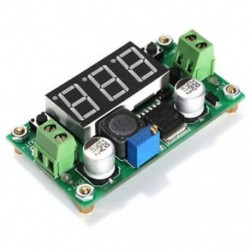
1. Signal PWM LCD Generator
Module Highlights:1.LCD display frequency and duty cycle, very clear, PWM output can be set to the frequency and duty cycle;
Wide frequency range, high precision;
Serial communication, TTL levelFirst, the module descriptionPWM output, you can set the frequency, duty cycle;Frequency is divided into four ranges, automatic switching:
XXX (no decimal point): the smallest unit is 1Hz, the value range of 1Hz ~ 999Hz;
X.XX (decimal point in the hundred) the smallest unit is 0.01Khz, the range of 1.00Khz ~ 9.99Khz;
XX.X (decimal point in ten): the smallest unit is 0.1Khz; value range of 10.0KHz ~ 99.9KHz
X.X.X (decimal point in ten and hundred): the smallest unit is 1Khz; value range 1KHz ~ 150KHzfrequency display: 100 indicates PWM output 100Hz pulse; 1.01 indicates PWM output 1.01K pulse;54.1 indicates that the PWM output has a pulse of 54.1 kHz;1.2.4 indicates that the PWM output is 124 kHz pulse;Duty cycle range: 0 ~ 100% ;All set parameters, power-down automatically saved.Second, the parameter settingsThe module has four independent keys, used to set the frequency and duty cycle, support touch (increase or decrease a unit) and long press (fast increase or decrease), set the parameters automatically save, power down Not lost.Third, the module parameters:
Working voltage: 3.3 ~ 30V;
Frequency range: 1Hz ~ 150KHz;
Frequency accuracy: the accuracy in each range is about 2% ;
Signal load capacity: the output current can be about 5 ~ 30ma;
Output amplitude: PWM amplitude equal to the supply voltage;
Ambient temperature: -20 ~ 70 â„.Fourth, the scope of application:
Used as a square wave signal generator, generate square wave signal for experimental development and use;
Used to generate a square wave signal that controls the motor driver;
generate adjustable pulse for MCU use;
generate adjustable pulse, control the relevant circuit (PWM dimming speed and other applications).5, serial control (single-chip TTL level communication) Communication standard: 9600 bps Data bits: 8Stop bit: 1Check digit: noneFlow control: none1, set the frequency of the PWM"F101": Set the frequency to 101 HZ (001 to 999)"F1.05": set the frequency of 1.05 KHZ (1.00 ~ 9.99)"F10.5": Set the frequency to 10.5KHZ (10.0 ~ 99.9)"F1.0.5": set the frequency of 105KHZ (1.0.0 ~ 1.5.0)2, set the PWM duty cycle"DXXX": set the PWM duty cycle to XXX; (001 ~ 100)Such as D050, set the PWM duty cycle is 50% 3, read the set parametersSend a "read" string to read the set parameters. Set successfully return: DOWN;Setup failed to return: FALL.Package Included: 1 x PWM Pulse Frequency Duty Cycle Adjustable Module Square Wave Signal Generator2. 5V Trigger Time Delay LCD
Product Description:Relay module delay power off and trigger delay cycle timing circuit switch
Timing Range:0.01 sec~9999 min
This product lcd display, very clear, simple and easy to use, powerful, but please read user instructions carefully before using.
Product Highlights:
1. Display with LCD two columns, Can display parameters directly;
2. Trigger mode: high and low level,switch quantity.meet most of the needs.
3. Power supply: 6~30V, also supports micro USB 5.0V, very convenient.Anti back connection of power supply.
4. Parameters can be modified via UART.
5. Stop button to provide emergency stop function.
6. 5 minutes without any operation into a low-power state. Any action wake up.
7. OP/CL/LOP params can be modified individually
8. All parameters are automatically saved by power off.
Working Mode Introduction(P1~P7)
P1: After the signal is triggered, the relay conduction in OP time then disconnects; In the OP time, the signal is invalid.
P2: After the signal is triggered, the relay conduction in OP time then disconnects; In the OP time, the signal triggers a new timer.
P3: After the signal is triggered, the relay conduction in OP time then disconnects; In the OP time, signal trigger reset timer,relay disconnected and stop timing.
P4: When triggered, After the relay is disconnected from CL time, relay conduction OP time, after timing is complete, disconnect relay.
P5: When triggered, After the relay conduction op time, the relay disconnects the CL time, and then loops the above action, gives the signal again in the loop, relays disconnect, stops the timer, and the number of cycles (LOP) can be set;
P6: When triggered, After the relay conduction op time, the relay disconnects the CL time, and then loops the above action, signal is invalid in the loop, the number of cycles (LOP) can be set;
P7: Signal hold function: The signal is maintained, the timing is cleared, and the relay conduction; when the signal disappears, the relay disconnects after the timing OP; during the timing, there is another signal and the timing is cleared;Product Parameters:
1. Power Supply: 6V~30V and micro USB 5.0 V
2. Trigger signal source: High level(3.0V~24.0V),Low level(0.0V ~0.2V),Switch signal.
3. Maxmum Output load: DC 30V 5A and AC 220V 5A.
4. Static Current: 15mA Operating current: 50mA.
5. Service life: more than 100,000 times; working temperature: -40-85°C; size: 8.0*3.8*1.9cm.
6. Optocoupler isolation,Strong anti-interference ability, Industrial grade circuit board
Timing Range:
0.01 sec~9999 min
How to choose the timing range:
In the OP/CL parameter modification interface, press the STOP button shortly to select the timing range.
XXXX Timing range:1sec~9999sec
XXX.X Timing range:0.1sec~999.9sec
XX.XX Timing range:0.01sec~99.99sec
X.X.X.X Timing range:1min~999.9min
For example, if you want to set the OP to 3.2 seconds, move the decimal point to ten digits. LCD display 003.2
Parameter Description: OP on-time, CL off time, LOP cycle times (1 - 9999 times, "----" represents an infinite number of cycles)
Parameter Settings:
a) Press and hold the SET key to enter the setting interface;
b) First set the working mode, work mode flashes reminder, set the working mode by pressing the UP / DOWN keys;
c) Short press the SET button to select the working mode and enter the system parameter settings.
d) In the system parameter setting interface, press SET key to switch the system parameters to be modified, and press / long press UP/DOWN key to modify. (Note: Short press SET in P-1~P-3, P-7 mode is invalid);
e) In the OP/CL parameter modification interface, short press STOP to switch the timer unit (1s/0.1s/0.01s/1min);
f) After all parameters are set, press and hold the SET button for more than 2 seconds to release the hand, save the parameter settings and exit the setting interface1. Remote data upload and parameter setting functions:
The system supports UART parameter reading and writing functions;
UART9600,8,1CMDFunction
readRead system parameters
OP:xxxxOP:xxx.xOP:xx.xxOP:x.x.x.x 1s0.1s0.01s1 min
CL:xxxx CL:xxx.xCL:xx.xxCL:x.x.x.x1s0.1s0.01s1 min
LP:xxxxSettings Cycles
onRelay enable
offRelay disable
PXSet the working mode(P1~P7)Additional features:
a) Low-power state: In the running interface, by pressing the STOP button for a long time, the Low-power function is started or closed (L-P selects on to start the hibernation function, and off turns off the hibernation function);
b) Relay function selection: In the operation interface, by pressing the STOP button shortly, the relay function is started or closed, 'on' meets the conduction condition relay normally turns on, 'OFF' meets the conduction condition relay does not turn on; 'OFF' In the state, the system flashes 'OUT';
c) Parameter view: In the operation interface, short press the SET key to display the current parameter setting of the system, without affecting the normal operation of the system;
d) Display content switching: In P-5 P-6 mode, switch display content (run time/cycle number) by pressing DOWN key momentarily.
Package Included: 1 x DC5V Time Delay Relay Module Trigger Cycle Timming Circuit Switch Board USB LCD


Egyéb infó
PWM Pulse Frequency Square Wave Signal Generator Trigger Cycle Switch Time Delay
1. Signal PWM LCD Generator
Module Highlights:1.LCD display frequency and duty cycle, very clear, PWM output can be set to the frequency and duty cycle;
Wide frequency range, high precision;
Serial communication, TTL levelFirst, the module descriptionPWM output, you can set the frequency, duty cycle;Frequency is divided into four ranges, automatic switching:
XXX (no decimal point): the smallest unit is 1Hz, the value range of 1Hz ~ 999Hz;
X.XX (decimal point in the hundred) the smallest unit is 0.01Khz, the range of 1.00Khz ~ 9.99Khz;
XX.X (decimal point in ten): the smallest unit is 0.1Khz; value range of 10.0KHz ~ 99.9KHz
X.X.X (decimal point in ten and hundred): the smallest unit is 1Khz; value range 1KHz ~ 150KHzfrequency display: 100 indicates PWM output 100Hz pulse; 1.01 indicates PWM output 1.01K pulse;54.1 indicates that the PWM output has a pulse of 54.1 kHz;1.2.4 indicates that the PWM output is 124 kHz pulse;Duty cycle range: 0 ~ 100% ;All set parameters, power-down automatically saved.Second, the parameter settingsThe module has four independent keys, used to set the frequency and duty cycle, support touch (increase or decrease a unit) and long press (fast increase or decrease), set the parameters automatically save, power down Not lost.Third, the module parameters:
Working voltage: 3.3 ~ 30V;
Frequency range: 1Hz ~ 150KHz;
Frequency accuracy: the accuracy in each range is about 2% ;
Signal load capacity: the output current can be about 5 ~ 30ma;
Output amplitude: PWM amplitude equal to the supply voltage;
Ambient temperature: -20 ~ 70 â„.Fourth, the scope of application:
Used as a square wave signal generator, generate square wave signal for experimental development and use;
Used to generate a square wave signal that controls the motor driver;
generate adjustable pulse for MCU use;
generate adjustable pulse, control the relevant circuit (PWM dimming speed and other applications).5, serial control (single-chip TTL level communication) Communication standard: 9600 bps Data bits: 8Stop bit: 1Check digit: noneFlow control: none1, set the frequency of the PWM"F101": Set the frequency to 101 HZ (001 to 999)"F1.05": set the frequency of 1.05 KHZ (1.00 ~ 9.99)"F10.5": Set the frequency to 10.5KHZ (10.0 ~ 99.9)"F1.0.5": set the frequency of 105KHZ (1.0.0 ~ 1.5.0)2, set the PWM duty cycle"DXXX": set the PWM duty cycle to XXX; (001 ~ 100)Such as D050, set the PWM duty cycle is 50% 3, read the set parametersSend a "read" string to read the set parameters. Set successfully return: DOWN;Setup failed to return: FALL.Package Included: 1 x PWM Pulse Frequency Duty Cycle Adjustable Module Square Wave Signal Generator2. 5V Trigger Time Delay LCD
Product Description:Relay module delay power off and trigger delay cycle timing circuit switch
Timing Range:0.01 sec~9999 min
This product lcd display, very clear, simple and easy to use, powerful, but please read user instructions carefully before using.
Product Highlights:
1. Display with LCD two columns, Can display parameters directly;
2. Trigger mode: high and low level,switch quantity.meet most of the needs.
3. Power supply: 6~30V, also supports micro USB 5.0V, very convenient.Anti back connection of power supply.
4. Parameters can be modified via UART.
5. Stop button to provide emergency stop function.
6. 5 minutes without any operation into a low-power state. Any action wake up.
7. OP/CL/LOP params can be modified individually
8. All parameters are automatically saved by power off.
Working Mode Introduction(P1~P7)
P1: After the signal is triggered, the relay conduction in OP time then disconnects; In the OP time, the signal is invalid.
P2: After the signal is triggered, the relay conduction in OP time then disconnects; In the OP time, the signal triggers a new timer.
P3: After the signal is triggered, the relay conduction in OP time then disconnects; In the OP time, signal trigger reset timer,relay disconnected and stop timing.
P4: When triggered, After the relay is disconnected from CL time, relay conduction OP time, after timing is complete, disconnect relay.
P5: When triggered, After the relay conduction op time, the relay disconnects the CL time, and then loops the above action, gives the signal again in the loop, relays disconnect, stops the timer, and the number of cycles (LOP) can be set;
P6: When triggered, After the relay conduction op time, the relay disconnects the CL time, and then loops the above action, signal is invalid in the loop, the number of cycles (LOP) can be set;
P7: Signal hold function: The signal is maintained, the timing is cleared, and the relay conduction; when the signal disappears, the relay disconnects after the timing OP; during the timing, there is another signal and the timing is cleared;Product Parameters:
1. Power Supply: 6V~30V and micro USB 5.0 V
2. Trigger signal source: High level(3.0V~24.0V),Low level(0.0V ~0.2V),Switch signal.
3. Maxmum Output load: DC 30V 5A and AC 220V 5A.
4. Static Current: 15mA Operating current: 50mA.
5. Service life: more than 100,000 times; working temperature: -40-85°C; size: 8.0*3.8*1.9cm.
6. Optocoupler isolation,Strong anti-interference ability, Industrial grade circuit board
Timing Range:
0.01 sec~9999 min
How to choose the timing range:
In the OP/CL parameter modification interface, press the STOP button shortly to select the timing range.
XXXX Timing range:1sec~9999sec
XXX.X Timing range:0.1sec~999.9sec
XX.XX Timing range:0.01sec~99.99sec
X.X.X.X Timing range:1min~999.9min
For example, if you want to set the OP to 3.2 seconds, move the decimal point to ten digits. LCD display 003.2
Parameter Description: OP on-time, CL off time, LOP cycle times (1 - 9999 times, "----" represents an infinite number of cycles)
Parameter Settings:
a) Press and hold the SET key to enter the setting interface;
b) First set the working mode, work mode flashes reminder, set the working mode by pressing the UP / DOWN keys;
c) Short press the SET button to select the working mode and enter the system parameter settings.
d) In the system parameter setting interface, press SET key to switch the system parameters to be modified, and press / long press UP/DOWN key to modify. (Note: Short press SET in P-1~P-3, P-7 mode is invalid);
e) In the OP/CL parameter modification interface, short press STOP to switch the timer unit (1s/0.1s/0.01s/1min);
f) After all parameters are set, press and hold the SET button for more than 2 seconds to release the hand, save the parameter settings and exit the setting interface1. Remote data upload and parameter setting functions:
The system supports UART parameter reading and writing functions;
UART9600,8,1CMDFunction
readRead system parameters
OP:xxxxOP:xxx.xOP:xx.xxOP:x.x.x.x 1s0.1s0.01s1 min
CL:xxxx CL:xxx.xCL:xx.xxCL:x.x.x.x1s0.1s0.01s1 min
LP:xxxxSettings Cycles
onRelay enable
offRelay disable
PXSet the working mode(P1~P7)Additional features:
a) Low-power state: In the running interface, by pressing the STOP button for a long time, the Low-power function is started or closed (L-P selects on to start the hibernation function, and off turns off the hibernation function);
b) Relay function selection: In the operation interface, by pressing the STOP button shortly, the relay function is started or closed, 'on' meets the conduction condition relay normally turns on, 'OFF' meets the conduction condition relay does not turn on; 'OFF' In the state, the system flashes 'OUT';
c) Parameter view: In the operation interface, short press the SET key to display the current parameter setting of the system, without affecting the normal operation of the system;
d) Display content switching: In P-5 P-6 mode, switch display content (run time/cycle number) by pressing DOWN key momentarily.
Package Included: 1 x DC5V Time Delay Relay Module Trigger Cycle Timming Circuit Switch Board USB LCD
202323111014/1 - ali110 (281)
30 egyéb termék a kategóriából:
-

2 CH optocsatolóval (fekete) 1/2/4/8 Channel 5V relé kártya modul Optikai csatlakozó LED az Arduino PiC ARM AVR
172 Ft -71% 592 Ft
-

Kék Eco OBD2 Benzin energiafogyasztás üzemanyag-megtakarító tuning doboz Chip autós gázmegtakarításhoz jp
252 Ft -71% 870 Ft
-

530db 5 szín 8 méret 530x választékkészlet 2: 1 Hőre zsugorodó huzalcső cső elektromos csatlakozó kábel
1 061 Ft -71% 3 658 Ft
-

1,25 mm-es 1.1 / 1.25 mm-es hab Cannon Orifice-fúvókafej-menet Fúvóka-fúvóka a hóhabbal szemben
120 Ft -71% 413 Ft
-

100Pcs / Set 1 / 4W 0,25W 5% 1 K OHM Szénfilm ellenállás 1. osztályú postai eszköz 100Pcs / Set 1 / 4W 0.25W 5% 1 K OHM
57 Ft -71% 197 Ft
-

100db 0,25W 1 / 4w Watt 10K ohm 10Kohm fémfilm ellenállás 100000R 1% 100db 0.25W 1 / 4w Watt 10K ohm 10Kohm fémfilm
118 Ft -71% 407 Ft
-

HC-SR501 Infravörös PIR mozgásérzékelő modul Arduino Málna pi-hez Új HC-SR501 Infravörös PIR mozgásérzékelő modul
200 Ft -71% 688 Ft
-
5db AC 250V / 3A 125V / 6A ON-OFF SPDT 2 pozíció reteszelő kapcsoló 5db AC 250V / 3A 125V / 6A ON-OFF SPDT 2 pozíció
156 Ft -71% 537 Ft
-
10db 49A 55V IRFZ44N IRFZ44 teljesítménytranzisztor MOSFET N-csatorna Új 10db 49A 55V IRFZ44N IRFZ44
171 Ft -71% 589 Ft
-

Tételek 10db KW12-3 PCB mikrokapcsoló Micro görgős kar kar Nyissa ki a határérték kapcsolót Tételek 10db KW12-3 PCB
172 Ft -71% 594 Ft
-

3S 20A 12,6V Li-ion lítium akkumulátor 18650 Töltő PCB BMS védelmi tábla cellája 3S 20A 12,6V Li-ion lítium
193 Ft -71% 667 Ft
-
Sok 5db dupla oldalú 5x7 cm-es nyomtatott áramkör PCB Vero prototípus nyomtatás Sok 5db dupla oldalú 5x7 cm-es nyomtatott
205 Ft -71% 707 Ft
-

5Pc / Set 15mm 10K OHM terminál lineáris forgó ellenállás potenciométer és gombok 5Pc / Set 15mm 10K OHM terminál
204 Ft -71% 704 Ft
-

Automatikus hasznos csíptető kábel fogók Vezetékes csíptető vezetkábel kéziszerszámok Automatikus hasznos csíptető
201 Ft -71% 693 Ft
-

1 X Boost Buck DC állítható Step Up Down átalakító XL6009 modul feszültség 1 X Boost Buck DC állítható Step Up Down
216 Ft -71% 745 Ft
-

1 x STM32F103C8T6 ARM STM32 Minimális rendszerfejlesztő kártya modul az Arduino használata 1 x STM32F103C8T6 ARM STM32
286 Ft -71% 985 Ft
-
Állítható frissített DC-DC LM 2596 átalakító ütköző szabályozásozó teljesítmény modul 1PCS Állítható
292 Ft -71% 1 006 Ft
-
TEC1-12706 hűtőborda termoelektromos hűtő hűtő Peltier lemezmodul 12V 60W TEC1-12706 hűtőborda termoelektromos hűtő
299 Ft -71% 1 032 Ft
-

PWM-impulzus frekvenciaváltó-vezérlőjel utólagos modul LCD 3.3V-30V PWM-impulzus frekvenciaváltó-vezérlőjel
416 Ft -71% 1 433 Ft
-

KSD301 Termosztát kapcsoló 10A 250V - 105 Celsius fokon kapcsol
609 Ft -71% 2 099 Ft
-
PT100 platina resist hőmérséklet érzékelő vízálló
609 Ft -71% 2 099 Ft
-
2db 4PIN Láng infravörös érzékelő vevő modul
609 Ft -71% 2 099 Ft
-

Zöld LED Meter Mini digitális voltmérő DC 0 -99.9V
609 Ft -71% 2 099 Ft
-

Kék LED Panel Mini digitális voltmérő DC 0 -99.9V
609 Ft -71% 2 099 Ft
-

Sárga-110v 22 mm-es LED-es jelzőfény Pilótafény jelzőlámpa panel Piros zöld Kék Sárga fehér
66 Ft -71% 228 Ft
-

Green-220v 22 mm-es LED-es jelzőfény Pilótafény jelzőlámpa panel Piros zöld Kék Sárga fehér
66 Ft -71% 228 Ft
-

Sárga Krómozott 4 érintkezős 12 mm-es LED könnyű nyomógomb pillanatnyi kapcsoló vízálló 12V
125 Ft -71% 433 Ft
-

Kék Krómozott 4 érintkezős 12 mm-es LED könnyű nyomógomb pillanatnyi kapcsoló vízálló 12V
125 Ft -71% 433 Ft
-
4 CH optocsatolóval (kék) 1/2/4/8 Channel 5V relé kártya modul Optikai csatlakozó LED az Arduino PiC ARM AVR
359 Ft -71% 1 238 Ft
-

8 CH optocsatolóval (kék) 1/2/4/8 Channel 5V relé kártya modul Optikai csatlakozó LED az Arduino PiC ARM AVR
729 Ft -71% 2 514 Ft